Nations have Electrical standards & Codes which are the “bibles” for proper grounding. In each country these standards are designed to protect the public from electrical shocks and fire hazards only. It does not deal with the power quality issues.

However, there are recommended practices that meet the requirements for performance grounding which mitigate inherent power quality (PQ) concerns. For example the,
- IEEE Standard 1100-2005, “IEEE Recommended Practice for powering and Grounding Sensitive Electronic Equipment” (The Emerald Book).
- IEEE Standard 142-2007, “IEEE Recommended Practice for Grounding of Industrial and Commercial Power Systems” (The Green Book).
- FIPS-94, The “Federal Information Processing Standards”.

These Standards describe the two basic types of safe grounding as system grounding and equipment grounding.
Systems grounding involve grounding of electrical power and telecommunication systems. To “limit voltages imposed by lightning, line surges, or unintentional contact with higher voltage lines and… stabilize the voltage to earth during normal operation.
It also explains that “conductive materials enclosing electrical conductors or equipment, or forming part of such equipment, shall be connected to earth so as to limit the voltage to ground on these materials.”
The Standards requires equipment and equipment enclosure grounding to prevent people from receiving shocks when they touch the equipment or its enclosure.
Equipment grounding for power quality purposes require connecting microprocessor-controlled equipment to ground to provide a zero reference point.
Microprocessor-controlled equipment needs a zero reference point to operate properly and control noise. It is usually grounded to a ground ring or electrode driven into the ground.
Earthing power systems include grounding the utility’s and end user’s power systems
What are the components of the electrical power system involved in system grounding?
Power System
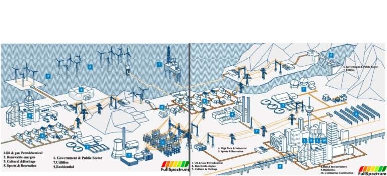
The entire electrical power system from the generator to the load can be divided into four levels: generation, transmission, distribution and secondary systems.
Each one of these systems is distinguished by the nominal operating voltage level. For example in Nigeria the generation voltage is usually at 11/16kV, transmission at 330/132kV, distribution 33/11kV, and secondary at 0.415/0.230kV.
All transmission and distribution systems are three phase.
Secondary systems are single phase but can be also be three phase.
Below shows a simplified utility power system from generation, transmission, distribution to secondary voltage levels.

Simplified utility power system
Each one of these power system levels has its own grounding requirements.
What are the grounding requirements for the utility power system?

Utility power system grounding
The utility power grounding system includes generation, transmission and distribution grounding systems.
Throughout the world, all utilities ground their generators.
However, in different parts of the world, utilities ground their transmission and distribution power systems according to the IT, TT or TN grounding systems. In the IT grounding system, they either do not bond their power system’s neutral to the generator ground or end user’s ground or instead ground it through impedance as shown below. This is common in parts of Europe.

IT earthing system
In Asia, TT system is adopted as shown below, they connect their power system’s neutral to the generator ground but not to the end user’s ground.

TT earthing system
In Nigeria & U.S, utilities primarily use the TN grounding system. In the TN grounding system, utilities bond their power system’s neutral to the generator’s ground and end user’s ground and at individual transmission and distribution tower as shown below

TN earthing system
The grounding of power systems is to provide a path for lightning and ground-fault currents. They set relays to detect ground-fault currents and isolate the source of the fault by sending signal to open appropriate breakers
The power system ground is also used as a reference for insulation coordination. The earth wires are strung above the power-line conductors and connected to the ground to shield the phase conductors from lightning strokes.
See below

Overhead Ground/earth wire
The transformer secondary circuit neutral is usually grounded. For example, the distribution transformer used to stepdown the distribution voltage of 11kV down to 415/240V, for use in homes has the neutral connected to the ground conductors.
Below shows the neutral of the service entrance distribution transformer ground wire.

Distribution transformer grounding at distribution pole
Utilities have various practices for grounding underground and overhead lines. For example, utilities should BUT often do not ground the shield of underground cables.
Below shows that lightning can strike a tree and produce electrical transients in the ground. Unground buried cables can transmit these electrical transients in the ground to sensitive electronic equipment, resulting in equipment damage.

Underground electrical transient
For overhead lines, it is the practice connecting the neutral to ground at the foot of the transmission tower, as shown in below. Some connect a wire to the neutral and run it along the tower to, usually, 2.4m (8-ft) ground rod (electrode) or to a counterpoise wire encased in concrete.

Grounding the transmission tower neutral allows linesmen to climb towers safely and diverts lightning strikes away from the transmission line.
It is standard practice to ground the neutral of a four-wire distribution system to meet code requirements. Most standards require that a distribution line must have a minimum of one ground rod per 400m (1/4 mile) and earth rod resistance of not more than 25ohms.
The grounded neutral provides a low-resistance path to earth for fault currents caused by a lightning strokes or a fault on the system.
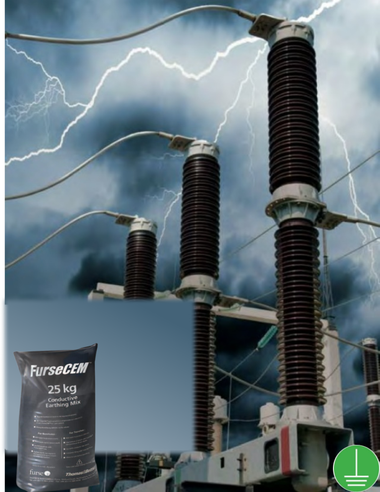
In addition, a well-grounded neutral reduces induced voltages from radio transmitters that can interfere with the power signals on the distribution line. They not only earth the distribution line neutral to the earth rods, but as shown below, also connect substation equipment like transformers to the earth grid.
Contact us


Victor Oyedu, FNSE, FNIEEE, CPQ
Power Quality and Energy Management Specialist.
Publisher at Afrienergyonline.com &
CEO, FullSpectrum Energy Solutions Limited, Nigeria