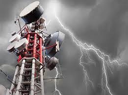
Lightning is one of nature’s most powerful and destructive phenomena, yet it is the most under rated weather hazard.
With awesome amount of electrical energy (measured upto over 200,000 Amperes), wrecking tremendous havoc to life and infrastructure on its trail across all sectors, despite its brief duration of fractions of a second.
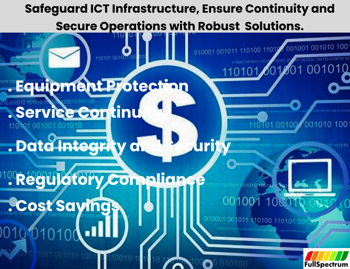
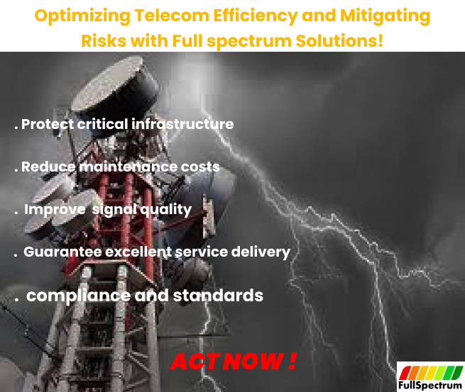
The consequences of both Structural (External) and Indirect (Surge) Lightning strikes result in catastrophic Health, Safety and Environmental issues with huge financial implications (costs).
To protect Structures and facilities effectively, the engineer must be abreast of the Lightning protection fundamentals and latest standards
We shall discuss basic design considerations for Structural (External) lightning protection
Structural Lightning Protection design considerations.
An effective lightning protection system should intercept, dispense and conduct safely the lightning energy to the ground without affecting the structure and the systems within.
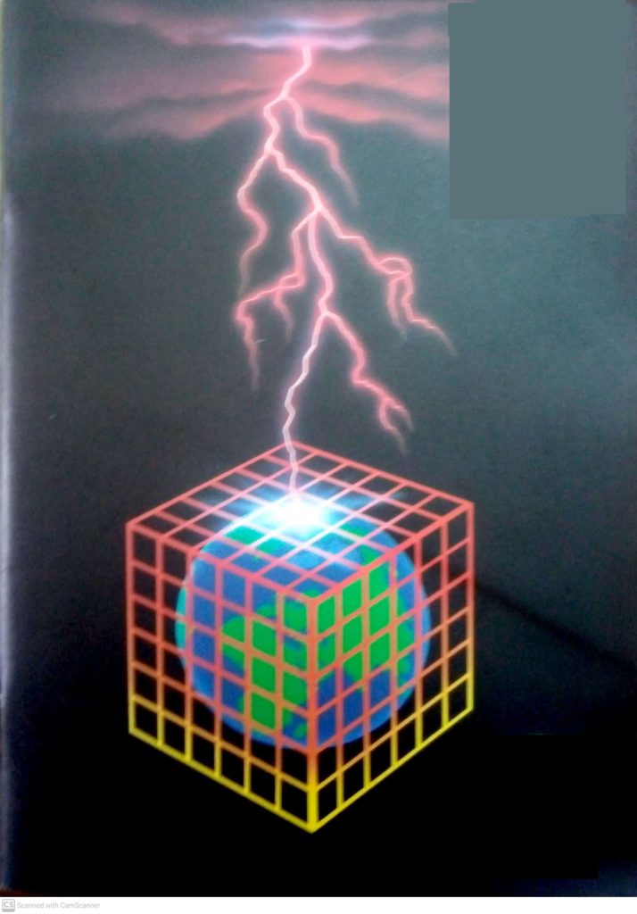
IEC / BS EN 62305 (Code of protection for structures against lightning) clearly advises strict adherence to the provision of a conventional Lightning protection system. (LPS) – to the total exclusion of any other device or system for that claim enhanced protection.
The main components of a conventional structural lightning protection system, in accordance with code are:
A. Air termination Network
B. Down Conductors
C. Earth Termination Network
D. Bonding (to prevent side flashing)Air termination network
A. Air termination Network
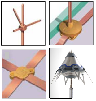
On high risk structures such as explosive factories, no part of the roof should be more than 2.5m from an air termination conductor. This is generally achieved by applying a 5m x 10m mesh to the roof.
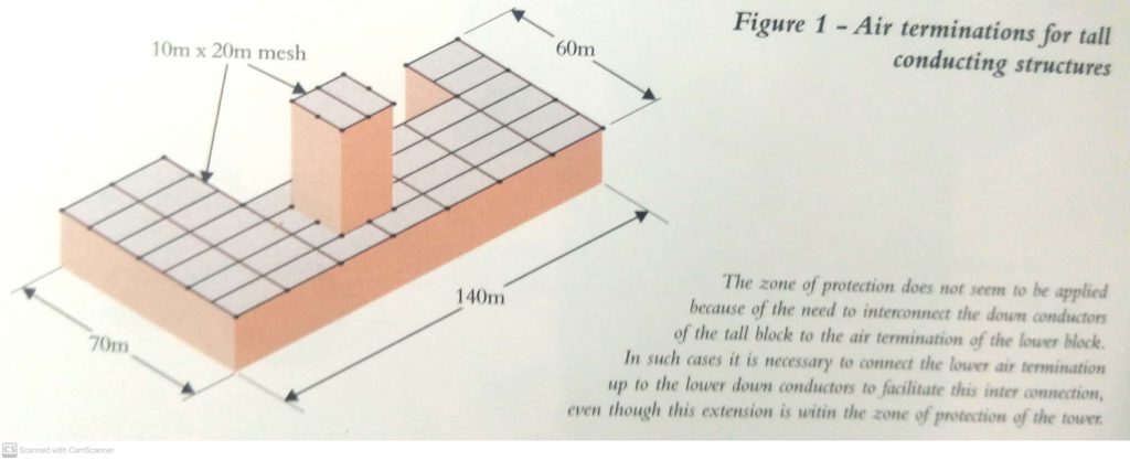
However, for most structures, a mesh of 10m x 20m is considered sufficient, giving a maximum distance from any part of the roof to the nearest conductor of 5m.
The ‘zone of protection’ offered by an air termination network is considered to be 300 for heights up to 20m. Above this height, the zone of protection is determined by the ‘rolling sphere method’.
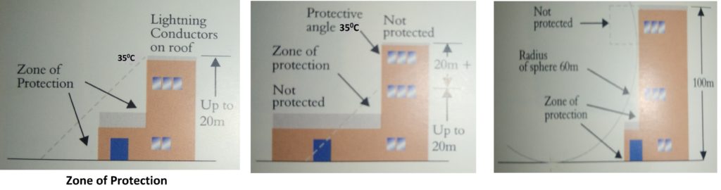
This involves rolling an imaginary sphere of 60m radius over a structure. The areas touched by the sphere are deemed to require protection. On tall structures, this can obviously include the sides of the building.
B. Down conductors
Down conductors- should be sited for every 20m or part thereof of the building perimeter at roof or ground level (whichever is greater).
These should be evenly spaced and distances apart of more than 20m avoided if possible.
If the building is above 20m in height or of an abnormal high risk this distance should be reduced to 10m.
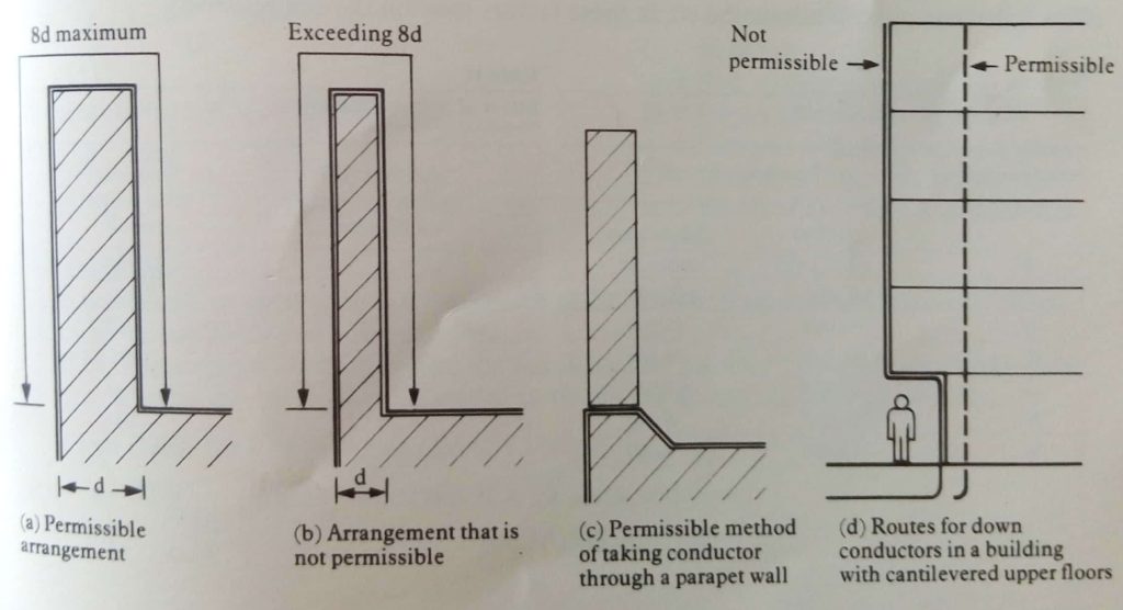
They should be routed as directly as possible from the air termination network to the earth termination network to avoid risks of side flashing. Re-entrant loops are also to be avoided. The code recommends that the length of conductor forming the loop should not exceed eight times the width of its open side.
The Code allows the use of ‘natural conductors’ such as rebars and structural steelworks, provided that they are electrically continuous and adequately earthed.
C. Earth termination networks
Each down conductor must have a separate earth termination. Moreover provision should be made in each down conductor, for disconnection from the earth for testing purposes. This is achieved with a test clamp
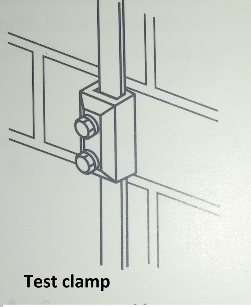
The Standards stipulates that the resistance to earth of the lightning protection system measured at any point should not exceed 10 ohms.
With the test clamp disconnected, the resistance of each individual earth should be no more than ten times the number of down conductors in the complete system. E.g for a system with 15 down conductors, the individual earth readings should be no more than 10 X 15 = 150 ohms.
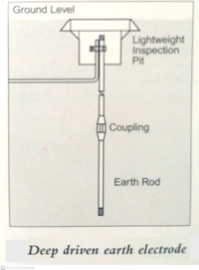
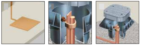
Several types of earth electrode are permissible, but by far the most commonly used are deep driven earth rods.
Code states that the combined earth rod length of a system should be no less than 6m whilst each individual earth rod should be no less than 1.2m in length.
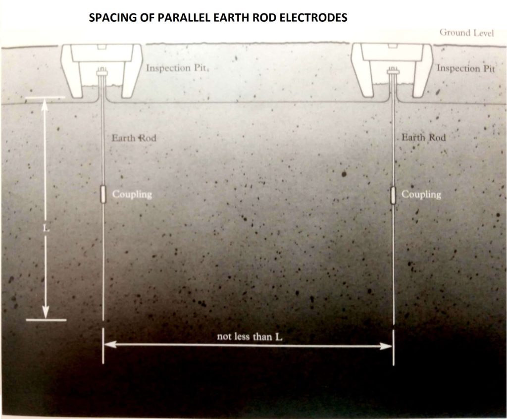
i. Parallel earth rod electrodes
Where ground conditions make deep driving of earth rods impossible, a matrix arrangement of rods coupled to one another by conductors can be used. If possible, the earth rods must be spaced at a distance at least equal to their driven depth.
Crow Foot
If earth rods cannot be driven in a parallel line a ‘crows Foot’ configuration can be used, ensuring that the spacing/depth ratio is still maintained.

Radial/ Bare Copper Electrode
Ground that has one metre depth of soil before encountering bedrock will best be suited to a buried radial electrode, provided the system is installed below the frost line and below the area that is subject to seasonal weather changes.
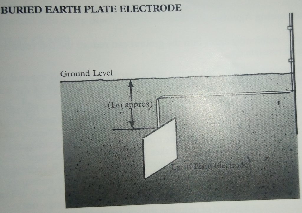
Solid plate or matt
Earth plates or matts can be buried instead of driving rod electrodes but installation is expensive and time consuming.
Reinforcing bars in foundations as natural earths
This is an economical method of using the mass of metal already underground in the form of the reinforcing bars, within the structure’s foundations. Precautions should be taken to ensure there is electrical continuity between these reinforcing bars and the earth/lightning protection connections above ground.
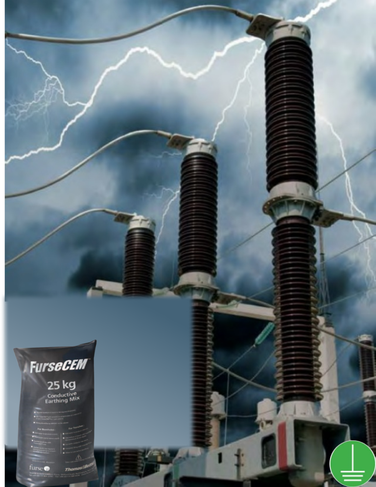
ii. Soil Conditioning Agents

High resistivity soil conditions can be overcome by backfilling earth rods with a suitable medium such as FurseCEM conductive concrete which effectively increases the diameter of the earth rod and hence its surface area, thus lowering resistance to earth.
D. Bonding
All metal work, including water pipes, gas pipes, handrails, air conditioning units, metal cladding, metal roofs etc. in the vicinity of the LPS must be bonded to it, to avoid the danger of side flashing.
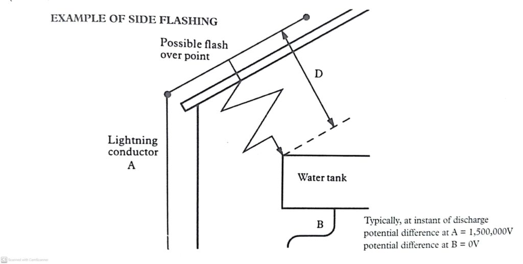
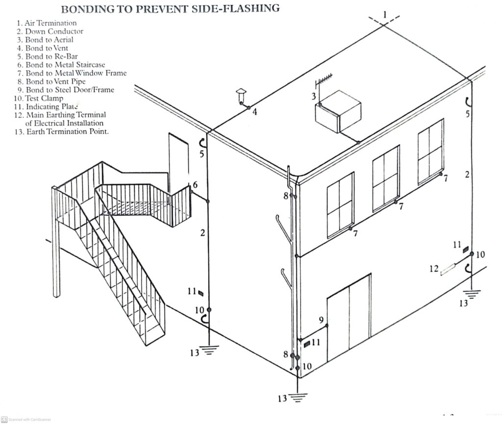
For the same reason, the LPS earth should be bonded to the main electrical earth, as well as any other earthing system present in the structure.
We provide FullSpectrum solutions to broad spectrum Lightning concerns from effective Designs, Procurement, Installations Maintenance to Commissioning irrespective of sector to international best practices.
FullSpectrum Energy is only a click or call away.


Victor Oyedu, FNSE, FNIEEE, CPQ.
Power Quality and Energy Management Specialist.
Publisher at Afrienergyonline.com
CEO, FullSpectrum Energy Solutions Limited, Nigeria.